Detailed, step-by-step instructions for disassembling and repairing the secondary shaft of a VAZ 2110 car. A diagram with details of the secondary shaft is presented.

The secondary shaft does not often fail, this is a rare occurrence, but it also happens. If you are faced with a breakdown, you can disassemble the shaft and, if necessary, replace worn gears and rings. Also, this procedure must be carried out if the gear shift is not clear - there are jamming. We removed and repaired the secondary shaft on a VAZ 2110 car. It will be more difficult to remove it from the car, since before that you will have to dismantle a lot of other parts from the car. To make it easier to repair the gearshift mechanism, see the detail diagram.
Output shaft details: diagram

| 1 - nut; | 14 - sliding clutch hub; |
| 2 - thrust plate; | 15 - a gear wheel of the 3rd transfer; |
| 3 - 5th gear synchronizer sliding sleeve; | 16 - a gear wheel of the 2nd transfer; |
| 4 - sliding clutch hub; | 17 - sliding coupling of the 1st and 2nd gear synchronizer with a reverse gear; |
| 5 - blocking ring of the synchronizer; | 18 - hub of the sliding clutch of the 1st and 2nd gears synchronizer; |
| 6 - a gear wheel of the 5th transfer; | 19 - synchronizer spring; |
| 7 - pinion bushing; | 20 - biscuit; |
| 8 - thrust washer; | 21 - retainer; |
| 9 - ball bearing; | 22 - gear wheel of the 1st transfer; |
| 10 - thrust washer; | 23 - leading gear wheel of the main transfer; |
| 11 - a gear wheel of the 4th transfer; | 24 - retaining ring; |
| 12 - locking ring of the synchronizer hub; | 25 - cylindrical roller bearing. |
| 13 - sliding sleeve of the synchronizer of the 3rd and 4th gears; |
In what order to repair the output shaft:
1. Before starting work, remove the output shaft from the gearbox.

2. Use a jaw-padded vise (pads must be made of soft metal) to grip the pinion shaft. To avoid damaging it, the vice must be tightened so that the device can be tilted by hand.
3. There is a circlip at the front end of the shaft, it is installed under the inner race of the front bearing. It must be removed.

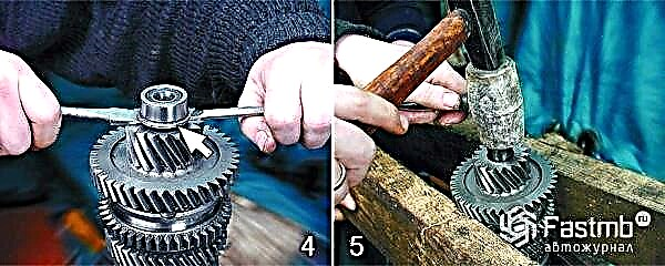
4. Use two screwdrivers to press the inner ring of the front bearing off the shaft. The collar of the ring faces the main gear of the final drive.
5. It is necessary to unclench the vice and rest the gear wheel of the 1st gear on two supports. Next, press the 1st gear from the shaft with the main gear of the main gear. This should be done with a hammer, but the blows should be applied through the wooden spacer.

6. Free the shaft from the final drive pinion. Note that the chamfer on the ID of the gear is facing the 1st gear.
7. Next, remove the 1st gear from the shaft. Its cone is located towards the synchronizer.

8. The locking ring (1) must be marked relative to the coupling (2). In the working position, the teeth of the ring run in to the teeth of the coupling, therefore, during the assembly process, the ring must be installed in the same position. Remove the 1st gear blocking ring from the synchronizer.
9. Again clamp the shaft in a vice and remove the locking circle of the synchronizer hub.

10. Using two large screwdrivers and applying force to the 2nd gear, press the 1st and 2nd gear synchronizer off the shaft splines.
11. Next, you need to remove the synchronizer with a blocking ring (1) of the 2nd gear, and then mark the ring (1) relative to the synchronizer coupling (2).

12. Free the shaft from the 2nd gear. You will see that the cone on the gear is facing towards the synchroniser. 13. With the shaft upside down, using two large screwdrivers, press the rear bearing off the shaft, the open side of which is directed towards the 4th gear.

14. Remove the thrust washer.
15. Remove the 4th gear. Take into account that the cone on the gear is facing towards the synchroniser.

16. Make a marking of the locking ring (1) in relation to the coupling (2) of the synchronizer. Then remove the 4th gear synchronizer blocking circle.
17. The retaining ring of the synchronizer hub must also be removed.

18. Next, you should unclench the vice, rest the gear wheel of the 3rd gear on two supports and through the soft gasket, hitting with a hammer, press the synchronizer of the 3rd and 4th gears from the shaft splines.
19. The synchroniser with the 3rd gear locking ring must be removed and the circle (1) marked with respect to the synchroniser sleeve (2). Note that the groove on the clutch faces the 3rd gear.

20. Remove the 3rd gear. Note that the cone on the gear is facing the synchronizer.
21. Take the output shaft parts, clean them well, rinse and dry.
22. Check the condition of the shaft. If you find pitting (pits) on the bearing journals or signs of wear, the shaft should be replaced.
23. Check the condition of the gears. If there are chipping and chipping of teeth, as well as scoring in the internal holes, the working surface of the teeth is worn out, then the gears must be replaced. In the case when the spline rim is significantly crumpled at the ends of the teeth or chips are found, the gears also require replacement.
24. It is necessary to check how easily the bearing rotates. According to the standards, the radial clearance in the bearing should be no more than 0.04 mm, therefore, if the raceways or balls are faulty, and also if a play has formed in the bearing, it must be replaced with a new one.
25. Check the condition of the locking rings of the synchronizers. If the cones are significantly worn out, and there are chips and nicks on the gear rims, then the locking rings must be replaced.
26. The gap between the gears and the corresponding locking rings must also be carefully checked. Place the locking ring tightly on the cone of the corresponding gear, turn it several times (“rub” against the cone) and measure the gap with a flat feeler gauge. It must be at least 0.6 mm. If there is less, replace the locking ring.
27. When you change the locking ring, be sure to check the gap between the gear and the new circle. Put a ring on the gear cone and shake it, there should not be the slightest backlash.
28. Thrust rings can also be deformed, have scuffs, retaining rings can lose their elasticity, and in the presence of such defects, replacement is required.

29. Before proceeding with the assembly of the output shaft, it is necessary to clean its oil channels.
30. The order of assembling the output shaft is reverse to disassembly. The old locking rings are installed accordingly with the previously made marks. New ones must be installed so that the small projections on the ring (there are no teeth) coincide with the grooves of the synchronizer hub (latches are also installed there).
31. To press in the rear shaft bearing, a suitable mandrel must be used; force is required only on the inner ring of the bearing.

32. Before starting the installation of the inner ring of the front bearing, install the retaining ring, and then, using the required mandrel, press the inner ring of the bearing against the stop into the retaining ring.
33. After the assembly is completed, check the operation of the synchronizers. Move the clutch manually to the position of engaging the corresponding gears, everything should be clearly included.